I have wanted to build a sundial for a long time. Recently, I got inspired by Reinhold Kriegler’s brilliant reflected sundial. For his own pages (in German) see the following:
There is a brief paragraph about reflection sundials on Wikpedia here. And there is a wonderful video presentation by Jackie Jones for the British Sundial Society.
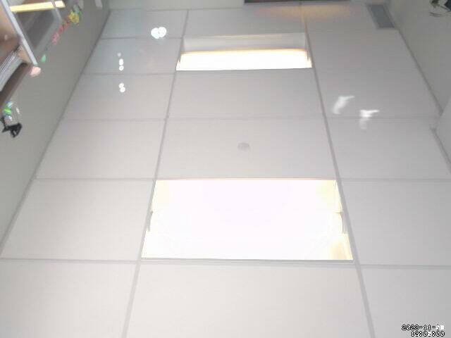
To get started, I filmed some timelapse footage of a reflected spot in my office between 10:00 and 14:00 EST. These video clips show two dots moving, as I’m playing around with various mirrors.
The plan is to create the whole sundial layout virtually, working from photos of the timelapse. The current goal is to reproduce the locations of the reflected spot on the timelapse in software. Once that is complete, I’ll have a sense of how much ceiling space the dial will require. This will impact the design of the final dial.
I asked Paco Estrada for some advice about how to correct the stills from the webcam to account for the perspective. He recommended that I look in to:
This turned up the following ImageMagick documentation: distort perspective. The next steps from here are to experiment with:
# Get photos from officebox
    rsync -avz ts-officebox:/archive/Webcam-Ceiling/ /home/pgadey/Pictures/Webcam-Ceiling/

    A good time frame on 2023-10-04: 10:35 to 13:58
    A good time frame on 2023-10-19: 10:37 to 13:41

    Get the snapshots between a particular pair of times:
            ls 2023-10-04T*.jpg | sed -n '/10:30/,/14:00/p'

    Copy over the good snapshots:
            cd ./snapshots/
            cp -v $(ls 2023-10-04T*.jpg | sed -n '/10:30:00/,/14:00:00/p') ../good-day/

    Make an mp4 out of them:
            cat *.jpg | ffmpeg -f image2pipe -i - output.mkv
            ffmpeg -i output.mkv -codec copy output.mp4
The most imporant line on a sundial is the noon line, or merdian. This lines marks where the sun passes at solar noon. It is the central line of a sundial.
We can use ImageMagick’s -evaluate-sequence max to pick out the brightest pixels.
To get the solar noon line for November, we first make a directory full of solar noon shots.
Then, take the brightest pixel of each image.
convert 2023-11-* -evaluate-sequence max solar-noon-november.jpg
Unfortunately, in November, the camera wobbled a little bit. Thus, the solar noon line is a little bit wobbly too! It appears at the left hand side of the image. And here is the noon line after transforming the perspective. (Notice the gap in the line. That’s a run of cloudy days.)
And this is straightforward to do with ImageMagick.
 The code to do so is here.
 #!/bin/bash

 Circle () {

 	# Circle filename x y r

 	image=$1;
 	X=$2;
 	Y=$3;
 	R=$(echo "$2 + 5" | bc);

 	echo "Creating a reference image with circle at (X,Y)=($X,$Y).";
 	convert -verbose -fill none -stroke blue -draw "circle $X,$Y $R,$Y" $image.jpg $image-circle.jpg

 }

 Circle ./2023-10-28T13:01:00-snapshot 120 120 5
And this is straightforward to do with ImageMagick.
One simply draws four circles.
To get the coordinates of the corners, I opened the image in GIMP and manually found the corners.
 The code to do so is here.
 #!/bin/bash

 Circle () {

 	# Circle filename x y r

 	image=$1;
 	X=$2;
 	Y=$3;
 	R=$(echo "$2 + 5" | bc);

 	echo "Creating a reference image with circle at (X,Y)=($X,$Y).";
 	mogrify -verbose -fill none -stroke blue -draw "circle $X,$Y $R,$Y" $image.jpg

 }

 cp ./2023-10-28T13:01:00-snapshot.jpg ./2023-10-28T13:01:00-snapshot-corners.jpg
 Circle ./2023-10-28T13:01:00-snapshot-corners 237 170 5
 Circle ./2023-10-28T13:01:00-snapshot-corners 220 255 5
 Circle ./2023-10-28T13:01:00-snapshot-corners 462 167 5
 Circle ./2023-10-28T13:01:00-snapshot-corners 481 256 5
-distort PerspectiveI need to think about this one more. It is not clear where these points out to map to. My first attempt gave me an even messier image.
 convert 2023-10-28T13:01:00-snapshot.jpg -alpha set -virtual-pixel transparent \
          -distort Perspective \
 	      '237,170 462,167 220,255 481,256 220,170 481,167 220,255 481,256' \
 	2023-10-28T13:01:00-snapshot-perspective.jpg
This is the weird output of that perspective transformation.

After playing with it a bit, I kept getting messier and weirder images. None of my attempted fixes made any difference. It turned out that I had the coodinates in a weird order and that messed up the quadrilateral.
 cp -v ./2023-10-28T13:01:00-snapshot.jpg ./2023-10-28T13:01:00-perspective-oops-1.jpg

 mogrify -verbose -draw 'fill none stroke red polygon 237,170 220,255 462,167
 481,256' ./2023-10-28T13:01:00-perspective-oops-1.jpg

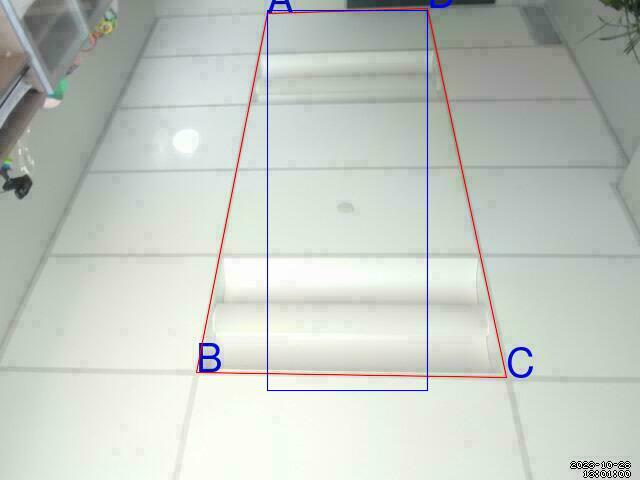
After this mix-up, I realized that it would be important to have the ability to label points. This lead to the following bit of code for labelling things crudely.

 #!/bin/bash

 Label () {
 	# Label filename x y text
 	image=$1;
 	X=$2;
 	Y=$3;
 	text=$4
 	mogrify -verbose -pointsize 40 -fill blue -draw "text $X,$Y \"$text\"" $image.jpg
 }

 cp -v ./2023-10-28T13:01:00-snapshot.jpg ./2023-10-28T13:01:00-labels.jpg

 image="./2023-10-28T13:01:00-labels"

 mogrify -verbose -draw 'fill none stroke red polygon 237,170 220,255 462,167 481,256' $image.jpg

 Label $image 237 170 "A"
 Label $image 220 255 "B"
 Label $image 481 256 "C"
 Label $image 426 167 "D"
Once I realized that I had mixed-up the order of the vertices, I thought that the perspective shift would work.
Unfortunately, more tests led to crazy looking results.
Eventually, I realized that I had totally mis-understood the syntax of -distort Perspective.
You want to send four points $(x_1, y_1), (x_2, y_2), (x_3, y_3), (x_4, y_4)$ to four new points $(a_1, b_1), (a_2, b_2), (a_3, b_3), (a_4, b_4)$.
I thought that one would just list ‘em “old points new points”. However, ImageMagick wants you to put them in the following order:
$$(x_1, y_1), (a_1, b_1), (x_2, y_2), (a_2, b_2), (x_3, y_3), (a_3, b_3), (x_4, y_4), (a_4, b_4)$$
This is the same information, but re-arranged a bit. It doesn’t fit with my intuition for function notation, so I had to create the following weird function to re-organize the arguments.
 Mangle () {
         echo "$1 $5 $2 $6 $3 $7 $8 $4"
 	}
This allows me to put the arguments in the order that I would expect.
The four points in the domain $POLY are listed first, and then the four points in the image $RECT are listed second.
This gives the following perspective transformation.
 convert 2023-10-28T13:01:00-snapshot.jpg -verbose -alpha set -virtual-pixel transparent \
           -distort Perspective \
               "$(Mangle $POLY $RECT)" \
         2023-10-28T13:01:00-snapshot-perspective.jpg

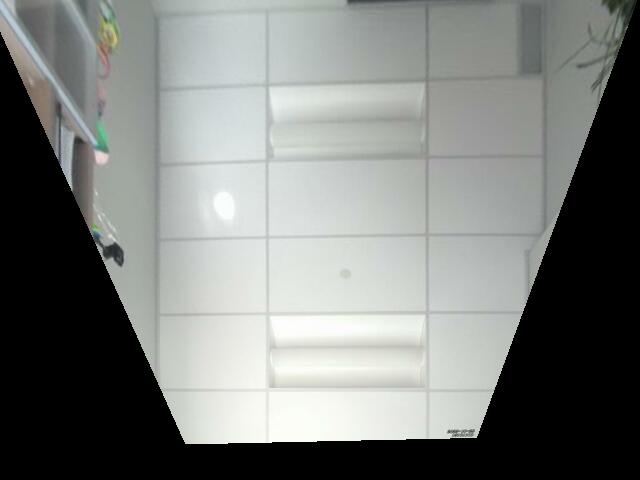
This perspective transformation misses some of the detail in the image because the dimensions of the final image remained fixed. For example, the transformation complete loses the vent in the top left of the image. I’m not sure how to correct for this issue; I would need to artificially enlarge the final image somehow. However, I can adjust the perspective transformation to map a different rectangle. This last idea led to the following.
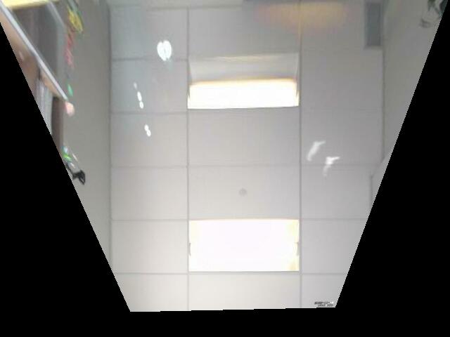
Now that I can change the perspective of a single frame, it is easy to produce the following timelapse.
One step of this project will be to layout a sundial in ImageMagick.
Let’s start with a simple clock face.
Modifying the -draw examples is one place to start.
 convert -size 100x100 xc:none -fill white -stroke red \
 -draw "line   20,50 25,25" \
 -draw "line   20,50 90,10" \
 imagemagick-lines-test.png
And you get something like this.

As a perverse test, here is a clock face generated in bash using bc.
 #!/bin/bash

 DRAW="convert -size 100x100 xc:none -fill white -stroke red \\"

 for k in $(seq 1 12); do
 DRAW="$DRAW \n -draw \"line   50,50 $(echo "scale=2; 50 + 30*s(((8*a(1))/12)*$k)" | bc --mathlib),$(echo "scale=2; 50 + 30*c(((8*a(1))/12)*$k)" | bc --mathlib)\" \\"
 done

 echo -e "$DRAW \n clock-face-test.png"
What is going on with that freaky term 30*s(((8*a(1))/12)*$k)?
In standard notation, it ought to read:
$$30\sin\left( \frac{8 \arctan(1)}{12} k \right) = 30\sin\left( \frac{2 \pi}{12} k \right).$$
The calculator bc does everything in radians, but doesn’t have a constant for $\pi$.
Thus, we use the term 8*a(1) or $8\arctan(1) = 2\pi$ in the denominator.
The script above will generate the following ImageMagick call.
 convert -size 100x100 xc:none -fill white -stroke red \
  -draw "line   50,50 64.70,76.10" \
  -draw "line   50,50 75.80,65.30" \
  -draw "line   50,50 79.70,50.60" \
  -draw "line   50,50 76.10,35.90" \
  -draw "line   50,50 65.30,24.50" \
  -draw "line   50,50 50.60,20.30" \
  -draw "line   50,50 35.90,23.60" \
  -draw "line   50,50 24.50,34.10" \
  -draw "line   50,50 20.30,48.80" \
  -draw "line   50,50 23.60,63.50" \
  -draw "line   50,50 34.10,75.20" \
  -draw "line   50,50 48.80,79.70" \
  clock-face-test.png
If we run that command, it will generate the following clock face.

Published: Oct 25, 2023
Last Modified: Dec 2, 2023
Thanks for reading! If you have any comments or questions about the content, please let me know. Anyone can contact me by email.